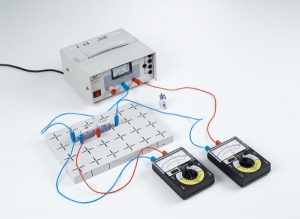
ELC-04-0ELC-01: Diodes
Virtually all aspects of electronic circuit technology rely on semiconductor components. The semiconductor diodes are among the simplest of these. They consist of a semiconductor crystal in which an n-conducting zone is adjacent to a p-conducting zone. Capture of the charge carriers, i.e. the electrons in the n-conducting and the “holes” in the p-conducting zones, forms a low-conductivity zone at the junction called the depletion layer. The size of this zone is increased when electrons or holes are removed from the depletion layer by an external electric field with a certain orientation. The direction of this electric field is called the reverse direction. Reversing the electric field drives the respective charge carriers into the depletion layer, allowing current to flow more easily through the diode.
| ELC-01-01 | Diodes (P4.1.3 ) | |||||
| ELC-01-02 | Recording the current-voltage characteristics of diodes (P4.1.3.1 ) | |||||
| ELC-01-03 | Recording the current-voltage characteristics of Zener diodes (Z-diodes) (P4.1.3.2) | |||||
| ELC-01-04 | Recording the current-voltage characteristics of light-emitting diodes (LED) (P4.1.3.3 ) | |||||
ELC-02: Diode circuits
Diodes, zener diodes (or Z-diodes) and light-emitting diodes are used today in virtually every electronic circuit.
| ELC-02-01 | Rectifying AC voltage using diodes (P4.1.4.1 ) | |||||
| ELC-02-02 | Voltage-limiting with a Z-diode (P4.1.4.2 ) | |||||
| ELC-02-03 | Testing polarity with light-emitting diodes (P4.1.4.3 ) | |||||
ELC-03: Transistor
Transistors are among the most important semiconductor components in electronic circuit technology. We distinguish between bipolar transistors, in which the electrons and holes are both involved in conducting current, and field-effect transistors, in which the current is carried solely by electrons. The electrodes of a bipolar transistor are called the emitter, the base and the collector. The transistor consists of a total of three n-conducting and p-conducting layers, in the order npn or pnp. The base layer, located in the middle, is so thin that charge carriers originating at one junction can cross to the other junction. In field-effect transistors, the conductivity of the current-carrying channel is changed using an electrical field, without applying power. The element which generates this field is called the gate. The input electrode of a field-effect transistor is known as the source, and the output electrode is called the drain.
![]()
| ELC-03-01 | Investigating the diode properties of transistor junctions (P4.1.5.1) | |||||
| ELC-03-02 | Recording the characteristics of a transistor (P4.1.5.2 ) | |||||
| ELC-03-03 | Recording the characteristics of a field-effect transistor (P4.1.5.3 ) | |||||
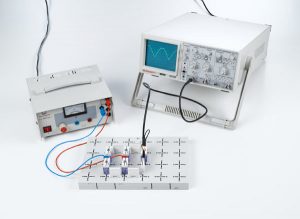
ELC-04: Transistor Circuit
Transistor circuits are investigated on the basis of a number of examples. These include the basic connections of a transistor as an amplifier, the transistor as a light-dependent or temperature-dependent electronic switch, the Wien bridge oscillator as an example of a sine-wave generator, the astable multivibrator, basic circuits with field-effect transistors as amplifiers as well as the field-effect transistor as a low-frequency switch.
![]()
| ELC-04-01 | The transistor as an amplifier (P4.1.6.1 ) | |||||
| ELC-04-02 | The transistor as a switch (P4.1.6.2 ) | |||||
| ELC-04-03 | The transistor as a sine-wave generator (oscillator) (P4.1.6.3 ) | |||||
| ELC-04-04 | The transistor as a function generator (P4.1.6.4 ) | |||||
| ELC-04-05 | The field-effect transistor as an amplifier (P4.1.6.5 ) | |||||
| ELC-04-06 | The field-effect transistor as a switch (P4.1.6.6 ) | |||||
ELC-05:
Optoelectronics deals with the application of the interactions between light and electrical charge carriers in optical and electronic devices. Optoelectronic arrangements consist of a light-emitting, a light-transmitting and a light-sensitive element. The light beam is controlled electrically.
![]()
| ELC-05-01 | Recording the characteristics of a phototransistor connected as a photodiode (P4.1.7.1 ) | |||||
| ELC-05-02 | Assembling a purely optical transmission line (P4.1.7.2 ) | |||||
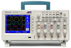
Oscilloscope
Module experiment : download here
Time-Response Identification of a Resistor–Capacitor (RC) Circuit
Module experiment : download here
Control of a Resistor–Capacitor (RC) Circuit
Module experiment : download here
[embedyt] https://www.youtube.com/watch?v=vYt51vz2Ctw[/embedyt]