ELE-01: Plate Capacitors
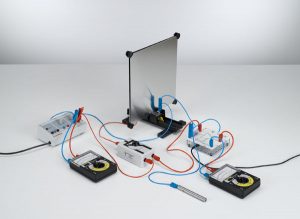
This experiment determines the total capacitance C of the demountable capacitor with the two plate pairs arranged at a fixed distance and connected first in parallel and then in series, compares these with the individual capacitances C1 and C2 of the two plate pairs.
Experiments:
| ELE-01-01 | Determining the capacitance of a plate capacitor – Measuring the charge with the electrometer amplifier (P3.1.7.1 ) | |||||
| ELE-01-02 | Parallel and series connection of capacitors – Measuring the charge with the electrometer amplifier (P3.1.7.2 ) | |||||
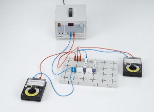
ELE-02: Kirchhoff’s laws
Experiments:
| ELE-02-01 | Measuring current and voltage at resistors connected in parallel and in series | |||||
| ELE-02-02 | Voltage division with a potentiometer | |||||
| ELE-02-03 | Principle of a Wheatstone bridge | |||||
ELE-03: Transformer

The primary and secondary voltages and the primary and secondary currents of a transformer under load are recorded as time-dependent quantities using the computer-based CASSY measuring system. The CASSY software determines the phase relationships between the four quantities directly and additionally calculates the time-dependent power values of the primary and secondary circuits.
Experiment:
| ELE-03-01 | Recording the voltage and current of a transformer under load as a function of time (P3.4.5.3 ) | |||||
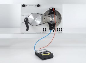
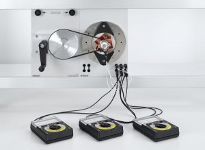
ELE-04: Basic experiment on electrical Machine
Electric generators
Electric generators exploit the principle of electromagnetic induction discovered by Faraday to convert mechanical into electrical energy. We distinguish between revolving-armature generators (excitation of the magnetic field in the stator, induction in the rotor) and revolving-field generators (excitation of the magnetic field in the rotor, induction in the stator).
Experiments:
| ELE-04-01-01 | Generating AC voltage using a revolving-field generator and a stationary-field generator | |||||
| ELE-04-01-02 | Generating DC voltage using a stationary-field generator | |||||
| ELE-04-01-03 | Generating AC voltage using a generator with electromagnetic rotating pole (power-plant generator) | |||||
| ELE-04-01-04 | Generating voltage with an AC-DC generator (generator with electromagnetic stationary pole) | |||||
| ELE-04-01-05 | Generating voltage using self-exciting generators | |||||
Electric Motor
Electric motors exploit the force acting on current-carrying conductors in magnetic fields to convert electrical energy into mechanical energy. We distinguish between asynchronous motors, in which the rotor is supplied with AC or DC voltage via a commutator, and synchronous motors, which have no commutator, and whose frequencies are synchronized with the frequency of the applied voltage.
Experiments:
| ELE-04-02-01 | Experiments on DC motor with two-pole rotor | |||||
| ELE-04-02-02 | Experiments on DC motor with three-pole rotor | |||||
| ELE-04-02-03 | Experiments with a universal motor in series and shunt connection | |||||
| ELE-04-02-04 | Assembling an AC synchronous motor (v) | |||||
Three- Phase Motor
In the real world, power is supplied mainly through the generation of three-phase AC, usually referred to simply as “threephase current”. Consequently, three-phase generators and motors are extremely significant in actual practice. In principle, their function is analogous to that of AC machines. As with AC machines, we differentiate between revolving-armature and revolving-field generators, and between asynchronous and synchronous motors.
Experiments:
| ELE-04-03-01 | Experiments with a three-phase revolving-armature generator | |||||
| ELE-04-03-02 | Experiments with a three-phase revolving-field generator | |||||
| ELE-04-03-03 | Comparing star and delta connections on a three-phase generator | |||||
| ELE-04-03-04 | Assembling synchronous and asynchronous three-phase motors (P3.5.4.4) | |||||
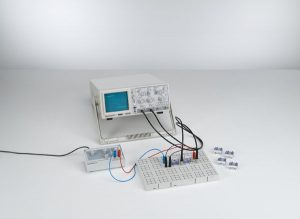
ELE-05: Circuit with capacitor
To investigate the behavior of capacitors in DC and AC circuits, the voltage UC at a capacitor is measured using a two-channel oscilloscope, and the current IC through the capacitor is additionally calculated from the voltage drop across a resistor R connected in series. Alternatively a Mobile-CASSY 2 is used. The circuits for conducting these measurements are assembled on a plug-in board using the STE plug-in system. A function generator is used as a voltage source with variable amplitude and variable frequency.
Experiments:
| ELE-05-01 | ||||||
| Circuit with capacitor | Charging and discharging a capacitor when switching DC on and off | |||||
| Determining the capacitive reactance of a capacitor in an AC circuit | ||||||
| ELE-05-02 | ||||||
| Circuit with coil | Measuring the current in a coil when switching DC on and off | |||||
| Determining the inductive reactance of a coil in an AC circuit | ||||||
| ELE-05-03 | ||||||
| Impedances | Determining the impedance in circuits with capacitors and ohmic resistors | |||||
| Determining the impedance in circuits with coils and ohmic resistors | ||||||
| Determining the impedance in circuits with capacitors and coils | ||||||
| ELE-05-04 | ||||||
| Measuring-bridge circuits | Determining capacitive reactance with a Wien measuring bridge | |||||
| Determining inductive reactance with a Maxwell measuring bridge | ||||||
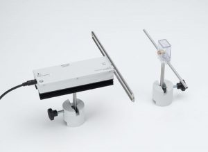
ELE-06: Decimeter Range Waves
It is possible to excite electromagnetic oscillations in a straight conductor in a manner analogous to an oscillator circuit. An oscillator of this type emits electromagnetic waves, and their radiated intensity is greatest when the conductor length is equivalent to exactly one half the wavelength (we call this a l/2 dipole). Experiments on this topic are particularly successful with wavelengths in the decimeter range. We can best demonstrate the existence of such decimeter waves using a second dipole which also has the length l/2, and from which the voltage is applied to an incandescent lamp or (via a high-frequency rectifier) to a measuring instrument.
E. Lecher (1890) was the first to suggest using two parallel wires for directional transmission of electromagnetic waves. Using such Lecher lines, as they are known today, electromagnetic waves can be transmitted to any point in space. They are measured along the line as a voltage U(x,t) propagating as a wave, or as a current I(x,t).
Experiments:
| Decimeter-range waves | ||||||
| ELE-06-01-a | Radiation characteristic and polarization of decimeter waves | |||||
| ELE-06-01-b | Amplitude modulation of decimeter waves | |||||
| ELE-06-01-c | Estimating the dielectric constant of water in the decimeter-wave range | |||||
| Propagation of decimeter-range waves along lines | ||||||
| ELE-06-02-a | Determining the current and voltage maxima on a Lecher line | |||||
| ELE-06-02-b | Investigating the current and voltage on a Lecher line with a loop dipole | |||||
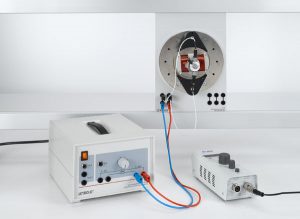
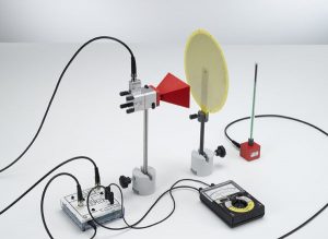
ELE-07: Microwaves
Microwaves are electromagnetic waves in the wavelength range between 0.1 mm and 100 mm. They are generated e.g. in a cavity resonator, whereby the frequency is determined by the volume of the cavity resonator. An E-field probe is used to detect the microwaves; this device measures the parallel component of the electric field. The output signal of the probe is proportional to the square of the field strength, and thus to the intensity.
Experiments:
| ELE-07-01 | Microwaves | |||||
| a | Directional characteristic and polarization of microwaves in front of a horn antenna | |||||
| b | Absorption of microwaves | |||||
| c | Interference of microwaves | |||||
| d | Diffraction of microwaves | |||||
| e | Refraction of microwaves | |||||
| f | Total reflection of microwaves | |||||
| ELE-07-02 | Propagation of microwaves along lines | |||||
| a | Guiding of microwaves along a Lecher line | |||||
| b | Qualitative demonstration of guiding of microwaves along a metal waveguide | |||||