OPT-01: Reflection, refraction
Frequently, the propagation of light can be adequately described simply by defining the ray path. Examples of this are the ray paths of light in mirrors, in lenses and in prisms using sectional models.
Experiment :
| OPT-01-01 | Reflection of light at straight and curved mirrors | |||||
| OPT-01-02 | Refraction of light at straight surfaces and investigation of ray paths in prisms and lenses | |||||
OPT-02: Laws of Imaging
The focal lengths of lenses are determined by a variety of means. The basis for these are the laws of imaging.
Experiment:
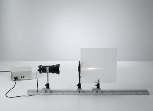
Diffraction
A photoelement with a narrow light opening is used to measure the diffraction intensities; this sensor can be moved perpendicularly to the optical axis on the optical bench, and its lateral position can be measured using a displacement transducer. The measured values are recorded and evaluated using the software CASSY Lab.
Coherence is the property of waves that enables them to exhibit stationary interference patterns. The spatial coherence of a light source can be examined in a Young’s double-slit interferometer. A light source illuminates a double slit with slit width b and distance g. If the partial beams emitted by the light source are coherent at the position of the two slits an interference pattern can be observed after the double slit.
| OPT-03-01 | Diffraction at a single slit – Recording and evaluating with VideoCom | |||||
| OPT-03-02 | Diffraction at a double slit and multiple slits – Recording and evaluating with VideoCom | |||||
| OPT-03-03 | Diffraction at a half-plane – Recording and evaluating with VideoCom | |||||
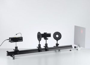
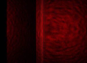
OPT-04: Two Beam Interference
In these experiments, two coherent light sources are generated by recreating three experiments of great historical significance.
In each of these experiments, the respective wavelength λ of the light used is determined by the distance d between two interference lines and the distance a of the (virtual) light sources.
| OPT-04-01 | Interference at a Fresnel’s mirror with an He-Ne laser | |||||
| OPT-04-02 | Lloyd’s mirror experiment with an He-Ne laser | |||||
| OPT-04-03 | Interference at Fresnel’s biprism with an He-Ne laser | |||||
OPT-05: Michelson interferometer
In a Michelson interferometer, an optical element divides a coherent light beam into two parts. The component beams travel different paths, are reflected into each other and finally recombined. As the two component beams have a fixed phase relationship with respect to each other, interference patterns can occur when they are superposed on each other. A change in the optical path length of one component beam alters the phase relation, and thus the interference pattern as well.
Thus, given a constant refractive index, a change in the interference pattern can be used to determine a change in the geometric path, e.g. changes in length due to heat expansion or the effects of electric or magnetic fields. When the geometric path is unchanged, then this configuration can be used to investigate changes in the refractive index due to variations e.g. in pressure, temperature and density.
| OPT-05-01 | Setting up a Michelson interferometer on the laser optics base plate | |||||
| OPT-05-02 | Determining the wavelength of the light of an He-Ne laser using a Michelson interferometer | |||||
OPT-06: Polarization
The fact that light can be polarized is important evidence of the transversal nature of light waves. Natural light is unpolarized. It consists of mutually independent, unordered waves, each of which has a specific polarization state. Polarization of light is the selection of waves having a specific polarization state.
Experiments:
| OPT-06-01 | Polarization of light through reflection at a glass plate | |||||
| OPT-06-02 | Fresnel’s laws of reflection | |||||
| OPT-06-03 | Polarization of light through scattering in an emulsion | |||||
| OPT-06-04 | Malus’ law | |||||
OPT-07: Birefringence
The validity of Snell’s law of refraction is based on the premise that light propagates in the refracting medium at the same velocity in all directions. In birefringent media, this condition is only fulfilled for the ordinary component of the light beam (the ordinary ray); the law of refraction does not apply for the extraordinary ray.
Experiments:
OPT-08: Faraday Effect
Transparent isotropic materials become optically active in a magnetic field; in other words, the plane of polarization of linearly polarized light rotates when passing through the material. M. Faraday discovered this effect in 1845 while seeking a relationship between magnetic and optical phenomena.
The angle of optical rotation of the plane of polarization is proportional to the illuminated length s and the magnetic field B.The proportionality constant V is known as Verdet’s constant, and depends on the wavelength λ of the light and the dispersion.
Experiment:
| OPT-08-01 | Faraday effect: determining Verdet’s constant for flint glass as a function of the wavelength | |||||
OPT-09: Quantitative and measuring methods of lighting Engineering
There are two types of physical quantities used to characterize the brightness of light sources: quantities which refer to the physics of radiation, which describe the energy radiation in terms of measurements, and quantities related to lighting engineering, which describe the subjectively perceived brightness under consideration of the spectral sensitivity of the human eye.
The first group includes the irradiance Ee, which is the radiated power per unit of area Φe. The corresponding unit of measure is watts per square meter. The comparable quantity in lighting engineering is illuminance E, i. e. the emitted luminous flux per unit of area Φ, and it is measured in lumens per square meter, or lux for short.
Experiment:
| OPT-09-01 | Determining the luminous intensity as a function of the distance from the light source – Recording and evaluating with CASSY | |||||
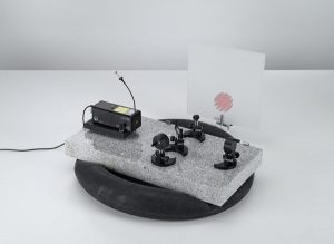
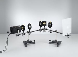
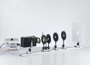
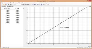
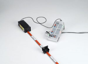
OPT-10: Measuring with an electronically modulated signal
The laser motion sensor S is used as a time-of-flight meter because it is also capable of outputting the time-of-flight t directly. The proportionality between the distance and the time-of-flight of light is confirmed, and the velocity of light is calculated.
Experiments:
Video:
[embedyt] https://www.youtube.com/watch?v=gIHcJTR_zio[/embedyt]